How to Build and Program Your First Self-Balancing Robot Kit
Complete technical guide — chassis assembly, MPU6050 gyroscope mounting, PID tuning, and upgrade paths for adult collectors building their first self-balancing robot kit from premium lego alternative for adults components.
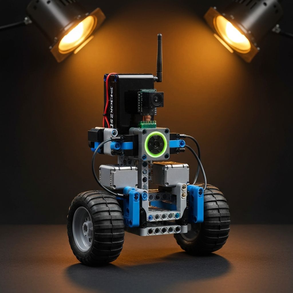
The MK-89201 Gyro-Bot series demands precision. 1450 pieces. Dual high-torque M-motors. 6-axis gyroscope integration. Building a self-balancing robot kit requires exact center-of-mass calculation and zero-latency motor response. This guide breaks down chassis assembly, sensor mounting, and PID tuning — no filler, just specs and steps.
Component Verification
Before assembly, audit your hardware. Missing pieces compromise structural integrity. Morebybourn commits to no missing pieces and will replace FREE missing / broken pieces to all orders.
- Motors: 2x 9V High-Torque DC Encoders (RPM: 300)
- Sensors: 1x MPU6050 6-Axis Gyro/Accelerometer
- Controller: 1x STM32-compatible Smart Hub (Bluetooth 5.0)
- Power: 1x 11.1V 2000mAh Li-Po Battery Pack
- Bricks: 1450 PCS Technic-compatible beams, pins, and axles
Choosing a high-quality lego alternative for adults ensures clutch power holds under dynamic loads. Loose pins cause motor backlash. Backlash ruins gyro stabilization.
Chassis Assembly
The chassis must be rigid. Flex causes sensor drift.
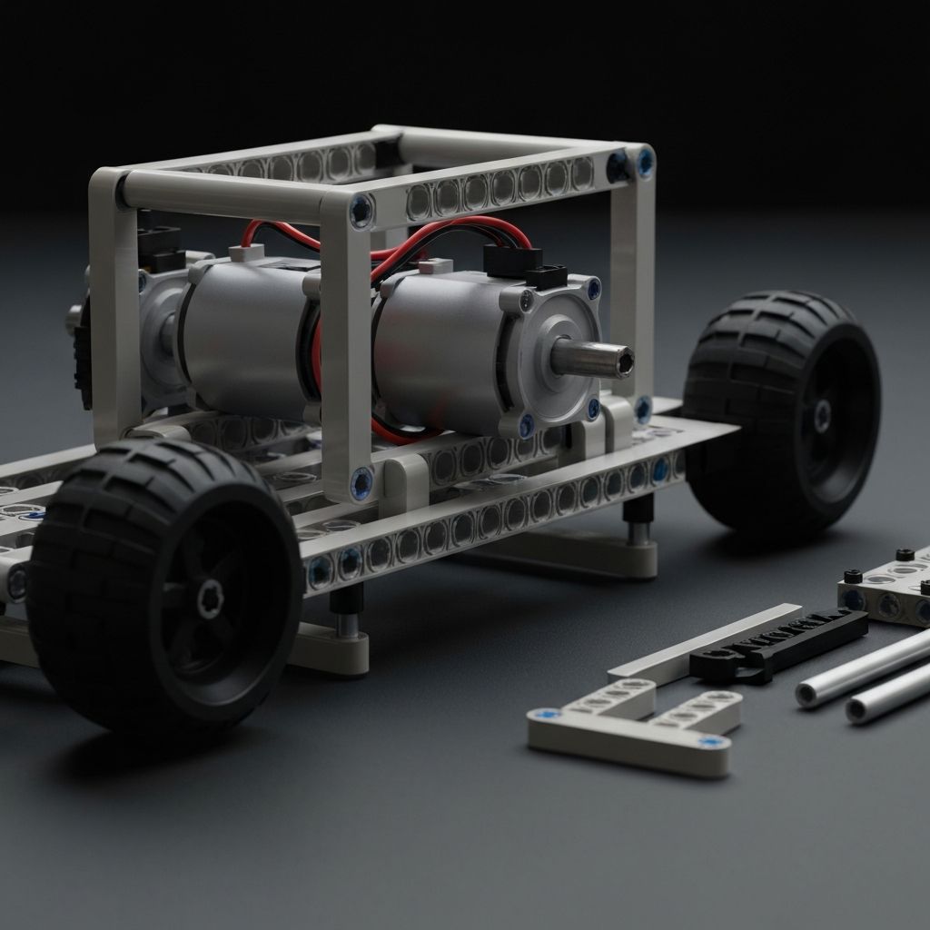
Base Frame Construction
- Connect 2x 15-module liftarms using 4x friction pins.
- Mount the 9V High-Torque motors horizontally. Secure with 3L axle pins.
- Install the 62.4mm x 20mm rubber tires on the motor output shafts.
- Reinforce the motor housing with 5x7 open center frames.
- Test axle rotation. Zero friction required.
Electronics Placement
- Mount the STM32 Smart Hub dead center above the wheel axle. Center of gravity must remain low.
- Secure the Li-Po battery directly behind the Smart Hub. Use 2x 3-module H-shape liftarms.
- Mount the MPU6050 sensor on the absolute vertical axis. Offset mounting guarantees algorithmic failure.
- Route motor cables. Secure with half-bushings. Cable interference with moving parts will shred wires.
Programming The Gyroscope
Hardware assembly is 40% of the build. Algorithm tuning is 60%. Your self-balancing robot kit relies on a PID (Proportional, Integral, Derivative) control loop.
Sensor Calibration
- Place the robot on a 100% flat surface.
- Initialize the Smart Hub.
- Run the MPU6050 zero-bias script.
- Record baseline X, Y, and Z values.
- Write offsets to the EEPROM.
Tuning The PID Loop
- Kp (Proportional): Increase until the robot oscillates rapidly around the vertical axis.
- Kd (Derivative): Increase to dampen the oscillation. The robot should resist being pushed.
- Ki (Integral): Increase slowly to correct long-term drift from battery weight or asymmetrical brick placement.
Test on hard floors. Carpets introduce variables the base algorithm cannot correct.
Common Build Mistakes
- Asymmetrical Weight: Adding decorative bricks to one side. The PID controller will burn out the opposite motor trying to compensate.
- Weak Clutch Power: Using inferior bricks. When the robot changes direction, loose frames flex. Gyro readings lag.
- Low Battery Voltage: Li-Po batteries below 9.5V drop motor torque. The robot will fall over regardless of PID tuning.
- Balance both sides: Add counterweights if decorative elements are necessary.
- Source quality bricks: Always use the best lego alternative for adults to guarantee tight tolerances.
- Charge fully: Always charge battery to 100% before testing. Monitor voltage during runs.
Upgrading Your Build
Once stabilization is achieved, expand functionality.
Obstacle Avoidance
Add Ultrasonic Sensors (HC-SR04) for autonomous navigation.
Remote Override
Install IR receivers for manual control when needed.
Height Expansion
Use 11-module liftarms to change center of gravity (requires PID retuning).
Source Your Components
Advanced motor kits and sensor mounts available now. We pay import fees so you don't have to!
Order via WhatsApp