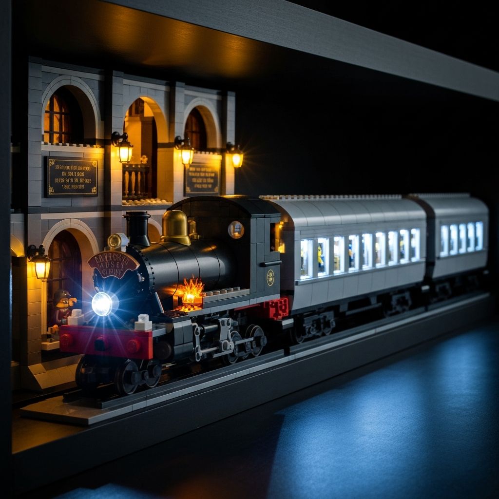
Hogwarts Express 76405 Harry Potter LED Lighting Kit: Complete Installation and Display Guide
The 5,129-piece Collector's Edition demands proper illumination. The Hogwarts Express 76405 Harry Potter LED Lighting Kit targets three distinct lighting zones — locomotive engine, passenger car interiors, and Platform 9¾ — using 0.1mm micro-wires that route between brick studs without modification. This guide covers component verification, zone-by-zone installation, power setup, and long-term display.
Kit Specifications at a Glance
Verify these specs against your 76405 build before starting. All measurements reference the Collector's Edition SKU L76405VERL available from Morebybourn.
Model Match
76405 Collector's Edition
Wire Diameter
0.1mm – 0.15mm
Power Interface
USB 5V
Battery Option
AA Battery Box (incl.)
Soldering Required
None — plug-and-play
LEGO Set Included
No — lighting kit only
Step 1 — Component Verification Before You Begin
Test every component before touching the model. Lay out expansion boards, LED strips, and micro-cables on a clean surface. Connect the USB cable to a power bank. Every LED should illuminate. Check each micro-plug clicks firmly into its expansion board port. A faulty connection discovered mid-build means full disassembly.
- 1Connect USB hub to power source and verify all boards receive voltage
- 2Test warm amber locomotive firebox LED strip — check flicker effect activates
- 3Test bright white headlamp micro-LED — verify beam direction
- 4Test cool white passenger car strips — confirm three independent zones
- 5Test warm yellow Platform 9¾ lamp LEDs — verify ambient spread
- 6Inspect all 0.1mm wire lengths for kinks or breaks before routing
Step 2 — Locomotive Engine Zone Installation
Begin with the locomotive. It is the most complex zone. The firebox and headlamp use different color temperatures and independent expansion board channels.
Firebox LEDs
Route the warm amber flickering strip through the cab floor. Lift the roof section. Feed the 0.1mm wire along the inner wall seam. Press bricks down firmly. The flicker effect simulates burning coal. Verify it activates on the correct expansion board channel before sealing the roof.
Front Headlamp LED
The bright white micro-LED seats in the boiler front opening. Route the wire back through the boiler length, following the interior wall. Secure at each stud gap. The headlamp should point forward at the track. Misalignment is visible from the front display angle.
Drive Wheel Ambient
The firebox glow provides ambient light to the drive wheels. No separate strip is needed. Ensure the firebox LED strip is positioned centrally in the cab so the warm light spills downward through the cab floor cutouts.
Cable Exit Route
Exit the locomotive wiring through the rear coupling connection point. Bundle both locomotive wires together. Route down the back side of the display track base toward the USB hub. Keep the bundle tight to avoid visible wire loops.
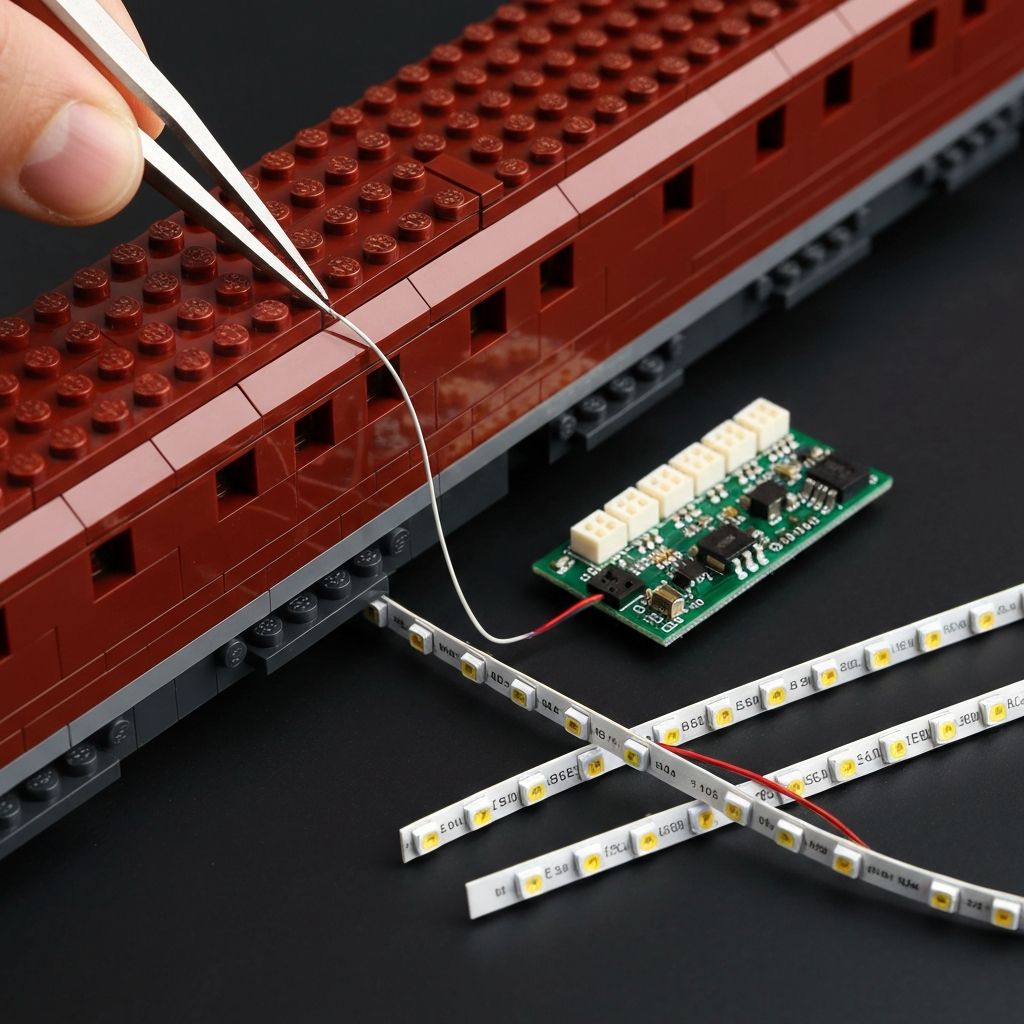
Step 3 — Passenger Car Interior Zones
Three passenger cars. Three independent light zones on the expansion board. Cool white overhead LEDs highlight the minifigures, sliding doors, luggage racks, and printed tile compartment details. Install one carriage fully before moving to the next.
- 1Remove the carriage roof panel. Set aside — do not force open.
- 2Route the cool white LED strip along the interior ceiling ridge. Press lightly against the inner roof tiles.
- 3Feed the 0.1mm wire through the roof tile seam line toward the rear wall.
- 4Exit the wire through the floor gap at the rear coupling end.
- 5Replace the roof panel. Confirm it seats fully — wires must not create a raised gap.
- 6Repeat for all three carriages before connecting wires to the hub.
Step 4 — Platform 9¾ Zone Installation
Platform 9¾ uses warm yellow LEDs to replicate vintage station lamp ambience. The archway structures and quote plaques are the primary display targets. This zone has the most architectural routing complexity.
Archway Lamp Strips
Position warm yellow LEDs inside the archway crown structures. The light should cast downward across the platform tiles. Verify shadow depth — overlapping arches create the depth effect.
Quote Plaque Lighting
Direct a focused micro-LED at the printed quote plaques. Route the wire under the platform tile layer. Exit through the rear of the platform base toward the USB hub.
Character Minifigure Area
The ambient station lighting illuminates the adult character minifigures positioned on the platform. No dedicated minifigure lighting strip is needed. Position figures under the archway light spread.
Step 5 — Power Routing and Hub Concealment
All wires converge at the USB hub. Route the bundle down the back of the display track base. The hub fits behind the Platform 9¾ station structure. Conceal the USB power cable through the case base if using a display case.
USB Power Option
- Connect USB hub to wall adapter (5V, 1A minimum)
- Or connect to USB power bank for portable display
- Route cable through display case base cutout
- Tape cable to rear of track base with low-tack tape
AA Battery Option
- Insert AA batteries (not included) into the included battery box
- Battery box fits behind the station structure
- Ideal for display cases without external cable routing
- Replace batteries every 40–60 hours of continuous use
Installation Do's and Don'ts
Do
- +Test all components before opening the model
- +Use fine-tip tweezers for 0.1mm wire routing
- +Route wires in the same direction as brick seam lines
- +Press bricks firmly and evenly after routing
- +Keep the expansion board accessible for brightness adjustment
- +Use the AA battery box for display cases
Don't
- -Force wires through tight brick gaps — re-route instead
- -Pull wires at right angles to the plug connector
- -Leave the USB hub in a position where it is visible
- -Run cables across the front display face of the model
- -Operate the kit with a power source above 5V USB
- -Ignore a loose micro-plug — it will fail under heat
Display Impact and STEM Learning Value
An unlit 76405 loses impact in low-light environments. The three contrasting color temperatures — warm amber firebox, cool white interiors, vintage yellow station — create depth. The model functions as a primary ambient light source on a display shelf. Pair with a custom acrylic case and route the USB cable through the base for a sealed display installation.
Parallel Circuits
Each lighting zone runs on its own expansion board channel. This is a practical introduction to parallel circuit topology. Load isolation per zone prevents a single LED failure from affecting other zones.
Wire Management
Routing 0.1mm cables through a 5,129-piece model develops fine motor discipline and spatial planning. These are transferable skills for electronics projects beyond building blocks.
Power Load Calculation
The kit draws under 500mA at 5V across all zones. Understanding load limits and matching the correct power source is fundamental applied electronics knowledge.
Morebybourn Guarantee
Custom-Fit Components
Exclusive components engineered for the 76405 model. No generic wire kits. Every LED strip, expansion board, and wire length is specified for this exact set.
Free Wire Replacement
Free replacement for any broken wires during installation. Submit a support request with your order number. We ship replacements directly at no charge.
Quality-Tested Boards
100% tested expansion boards. Every board is verified for voltage regulation and channel isolation before shipment.
No Hidden Fees
The total billed at checkout is the final amount. Tax and tariff inclusive. We pay these fees so you do not have to.
Ready to illuminate your Hogwarts Express 76405?
Order via WhatsApp for fast response, stock confirmation, and shipping details.
View Product — Order via WhatsAppFrequently Asked Questions
Does the Hogwarts Express 76405 LED lighting kit include the building model?▾
No. This is an electronics accessory kit only. The 76405 Collector's Edition building block set is sold separately.
What power source does the lighting kit use?▾
The kit operates on 5V USB power. Use a standard USB wall adapter, a USB power bank, or the included AA battery box. Batteries are not included in the kit.
Will installing the wires damage the bricks?▾
No. The micro-cables measure 0.1mm to 0.15mm. They sit in the gaps between standard brick studs without stress or deformation. Clutch power is fully maintained.
Can I still remove the passenger car roof after installation?▾
Yes. Wires are routed to allow continued roof removal and full access to interior compartments, minifigures, and printed tile details.
Is soldering required for this installation?▾
No. The kit is plug-and-play. All connections use micro-plugs and expansion boards. Installation requires patience and fine tweezers, not electronics expertise.